
My first retaining wall footing cracked within a year. Not because I cut corners. Because I did not fully understand what I was designing.
That mistake cost time, money, and a lot of stress.You do not have to go through that.
This guide covers everything: design ratios, load calculations, stability checks, and reinforcement steps.
I broke it down the way I needed it explained back then. Simple, step by step, and straight to the point.
Let’s get your footing right the first time.
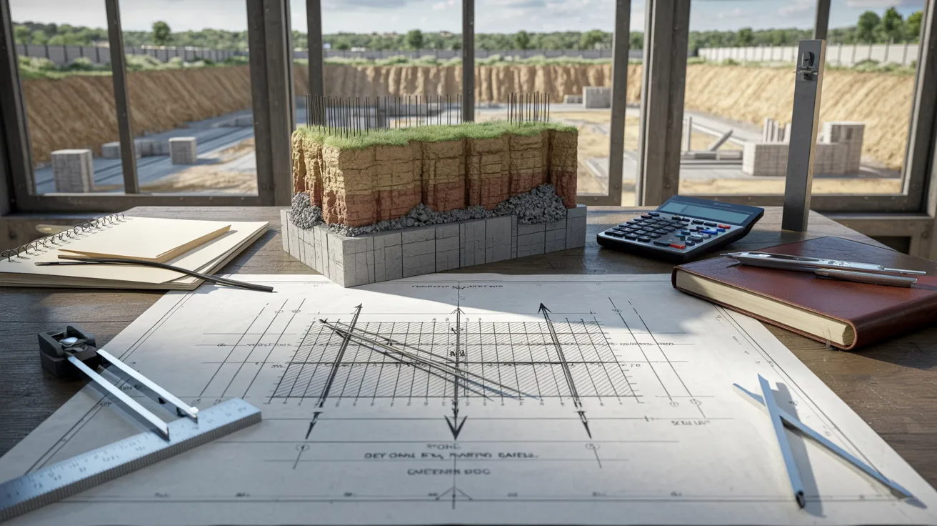
Understanding Retaining Wall Footing
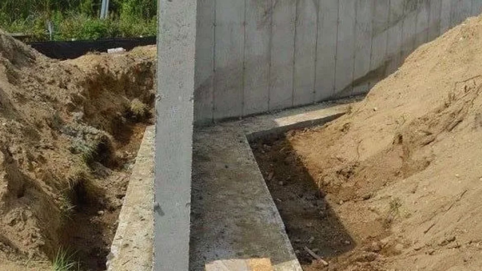
A retaining wall footing is the concrete base that sits beneath the wall and spreads its load into the ground.
It has to handle lateral earth pressure pushing from behind, the weight of the wall and soil above, and any extra loads on the surface.
Without a properly sized footing, the wall has nothing solid to rely on. The footing works with the stem to resist sliding, overturning, and settlement.
Its width, thickness, and depth all depend on soil conditions, wall height, and the total load the structure must carry.
Types of Retaining Wall Footings
The right footing type depends on your wall height, load conditions, and site setup.
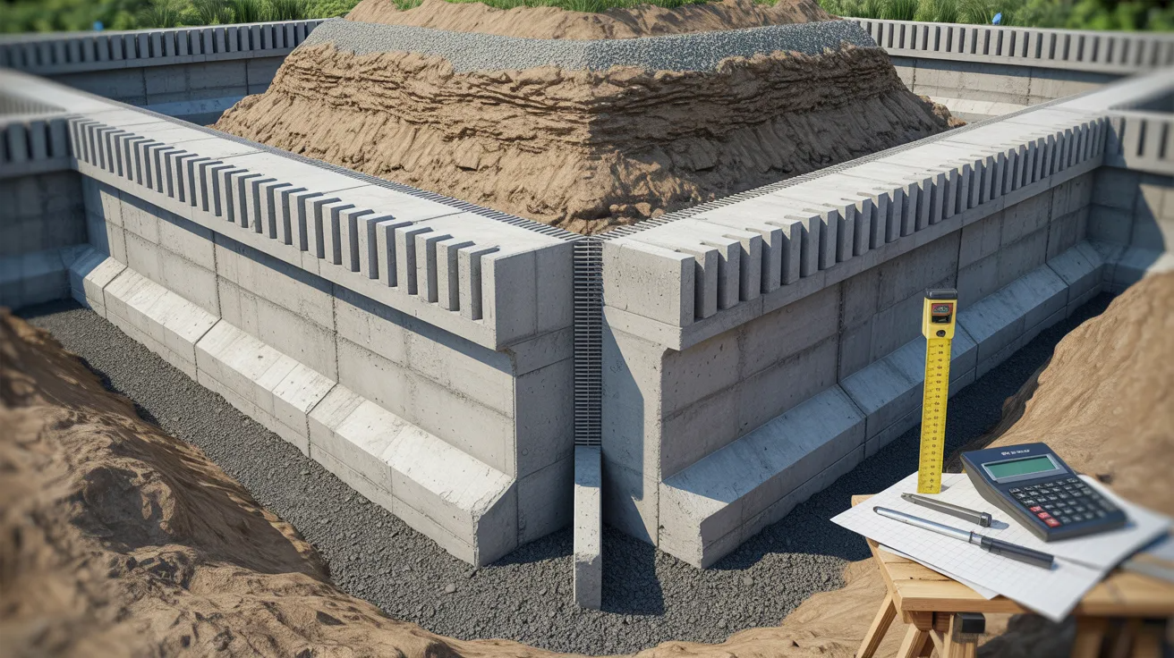
Cantilever Wall Footing
A cantilever footing has two parts: the heel and the toe. The heel extends back into the retained soil.
The toe projects forward in front of the wall. Soil weight on the heel helps resist overturning. This design works well for walls between 10 and 25 feet.
Both the footing and the stem bend under load, so steel placement is a key part of making this system work correctly.
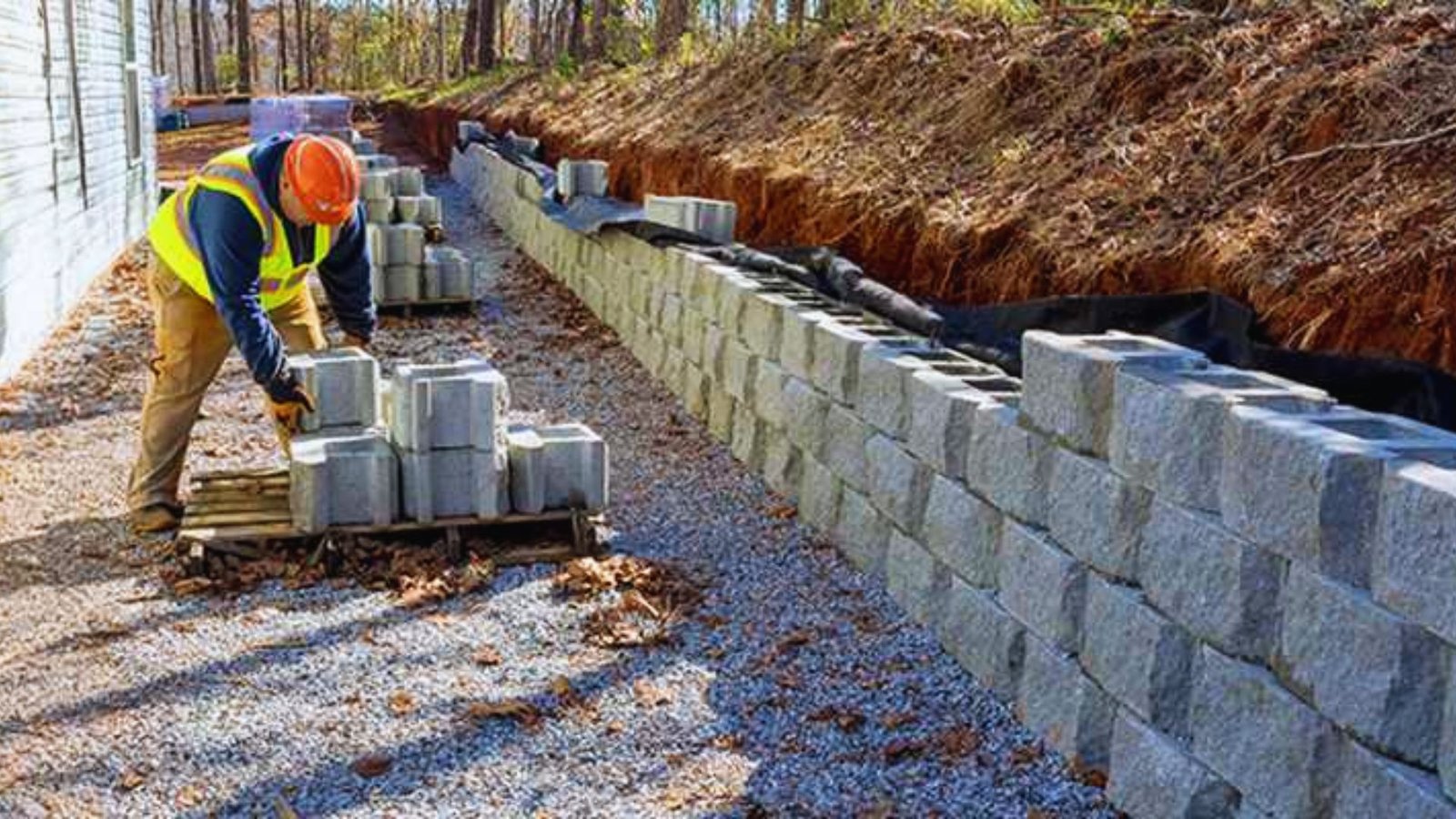
Gravity Wall Footing
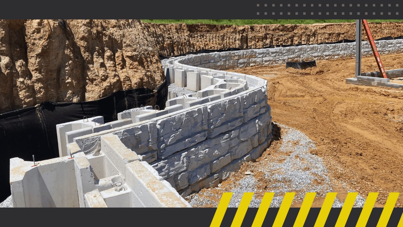
A gravity wall stays in place because of its own weight. The footing is wide and heavy by design.
It does not rely on much reinforcement because the mass of the wall resists sliding and overturning on its own. This type works best for shorter walls, usually under 10 feet.
Common materials include plain concrete, stone, and masonry. The footing must be wide enough to keep bearing pressure within the allowable limit for the soil below.
Anchored and Counterfort Wall Footings
Anchored walls use cables or rods tied back into the soil or rock behind the wall. Counterfort walls have triangular ribs connected to the back of the stem at regular intervals.
Both types handle tall or heavily loaded walls well. They distribute forces more evenly across the structure, which reduces bending in the stem and footing.
These designs are more involved to build but allow for thinner wall sections at greater heights.
Structural Considerations for Footing Design
Before you size any footing, you need to understand every force acting on it and confirm the structure can resist them all safely.
Load Analysis

Lateral earth pressure is the main force pushing against the back of the wall. Surcharge loads from driveways, buildings, or equipment sitting on the retained soil add pressure at the top.
The self-weight of the wall and the soil resting on the heel both contribute resisting forces. Hydrostatic pressure from water buildup behind the wall can be large if drainage is poor.
Every one of these loads must be calculated before you start sizing the footing.
Stability Checks
Three checks must pass before the design moves forward. The overturning factor of safety must be at least 2.0. The sliding factor of safety must reach 1.5 or higher.
The bearing factor of safety must be at least 3.0. If any of these fail, adjustments are needed.
You can widen the base, extend the heel, add a shear key beneath the footing, or change the toe length to shift how the loads distribute.
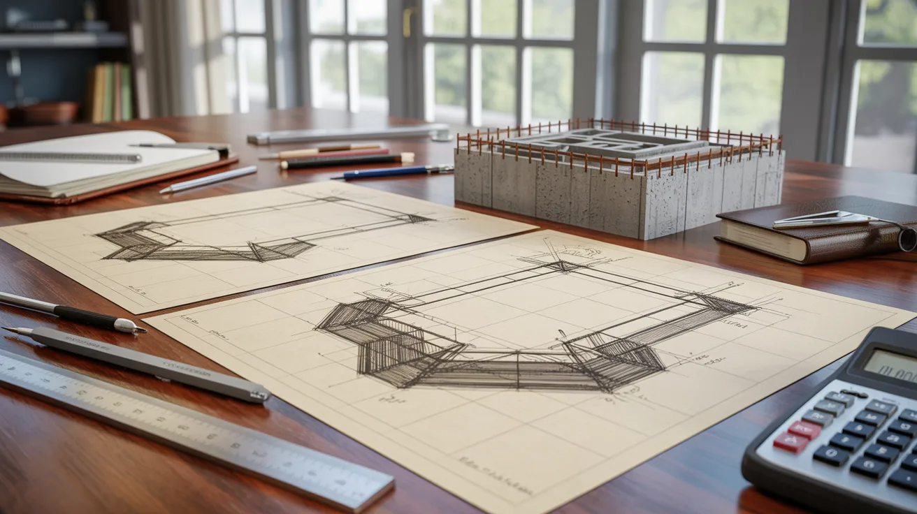
Preliminary Footing Dimensioning (With Calculations)
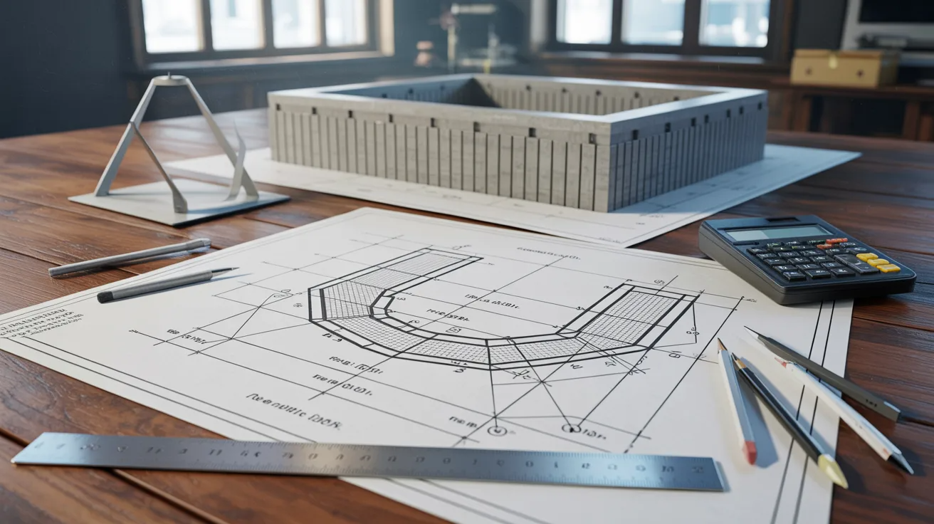
Starting with the right dimensions saves time and reduces the number of revision cycles before the design is finalized.
Recommended Design Ratios (ACI Guidelines)
ACI guidelines give you starting ratios based on wall height:
Base width: 0.4 to 0.7 times the wall height
Toe width: 1/4 to 1/3 of the base width
Base thickness: 0.07 to 0.1 times the wall height, with a minimum of 12 inches
Stem thickness: 0.07 to 0.12 times the wall height
These are starting points, not final answers. Adjust them once your load and stability calculations are complete.
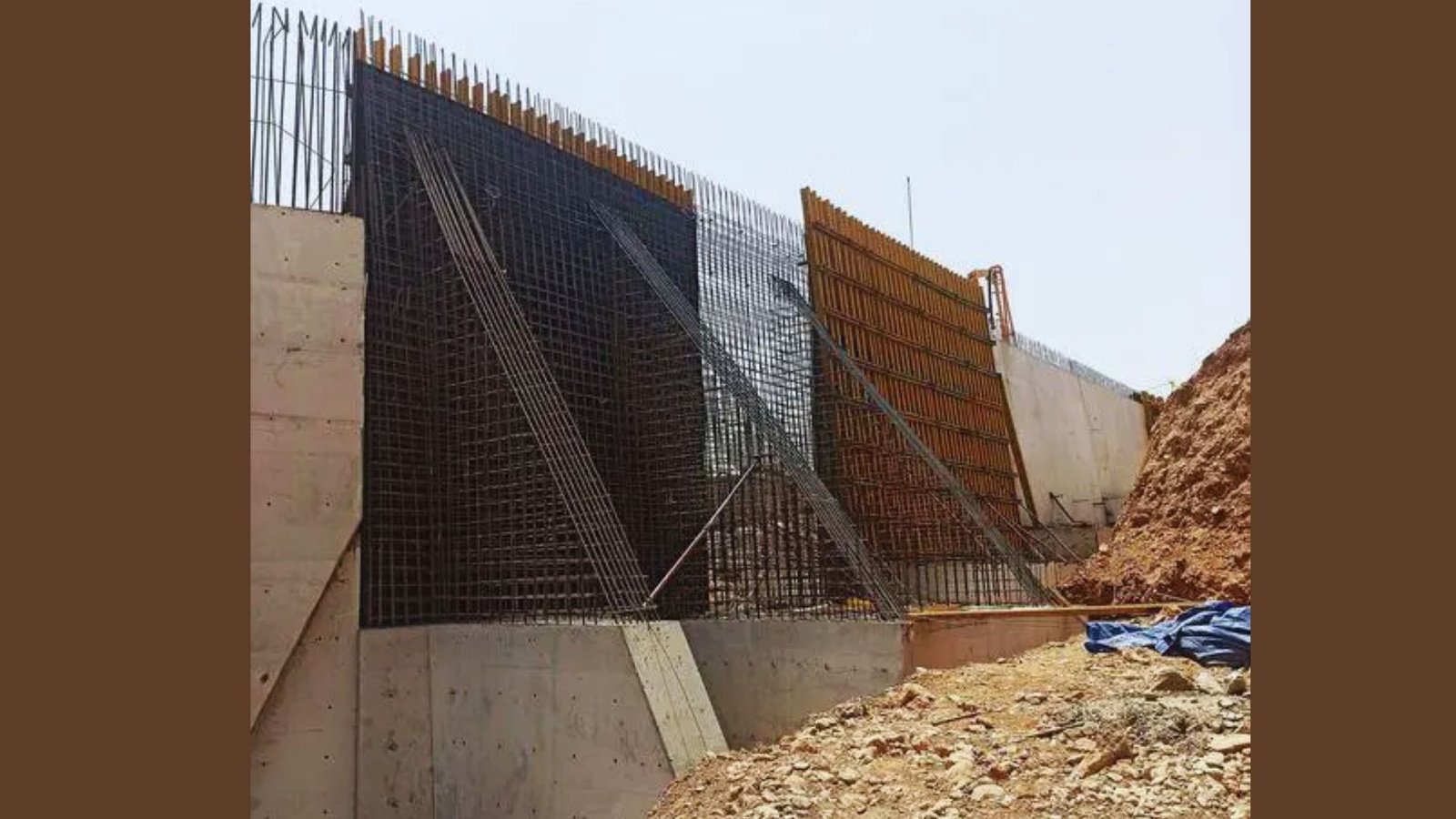
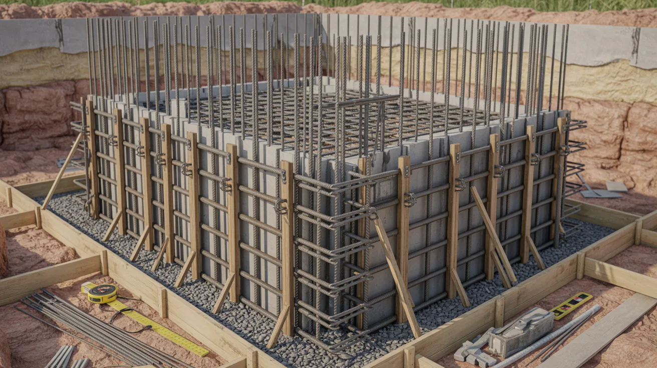
Reinforcement and Structural Design
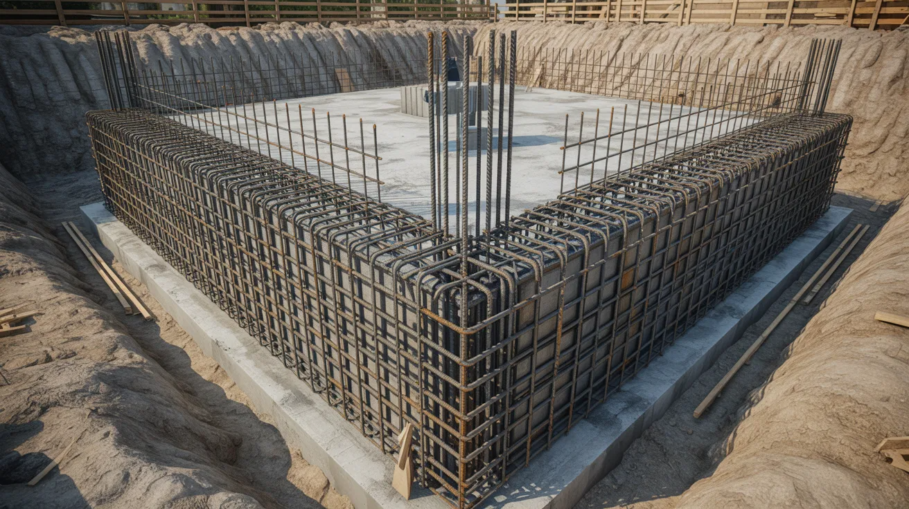
Once the footing geometry is confirmed, the steel must be designed to carry the bending and shear demands in every part of the structure.
Footing Reinforcement
Bottom steel in the footing resists tension under the toe, where upward soil pressure bends the section.
Top steel handles tension in the heel, where the soil load above bends the footing downward. ACI 318 minimum reinforcement ratios apply across the full footing.
All bars must be anchored into the stem with enough development length to transfer forces across the joint without slipping or causing cracks at the base.
Stem Design
The stem acts as a vertical cantilever, fixed at the base and free at the top. Lateral earth pressure and surcharge loads create bending moments and shear forces that increase toward the base.
The critical section for flexure is at the stem-footing connection. Shear is checked at a distance equal to the effective depth above the base.
The self-weight of the wall also adds axial load at this section, which must be included in the full demand calculation.
Toe and Heel Design
The toe extends in front of the stem and carries upward bearing pressure from the soil below. This creates an upward bending moment, so tension steel goes at the bottom face.
The heel extends behind the stem and carries the weight of retained soil pressing down on it. This bends the heel downward, placing tension at the top face.
Both sections must also pass a shear strength check to confirm the footing thickness is adequate without adding extra steel.
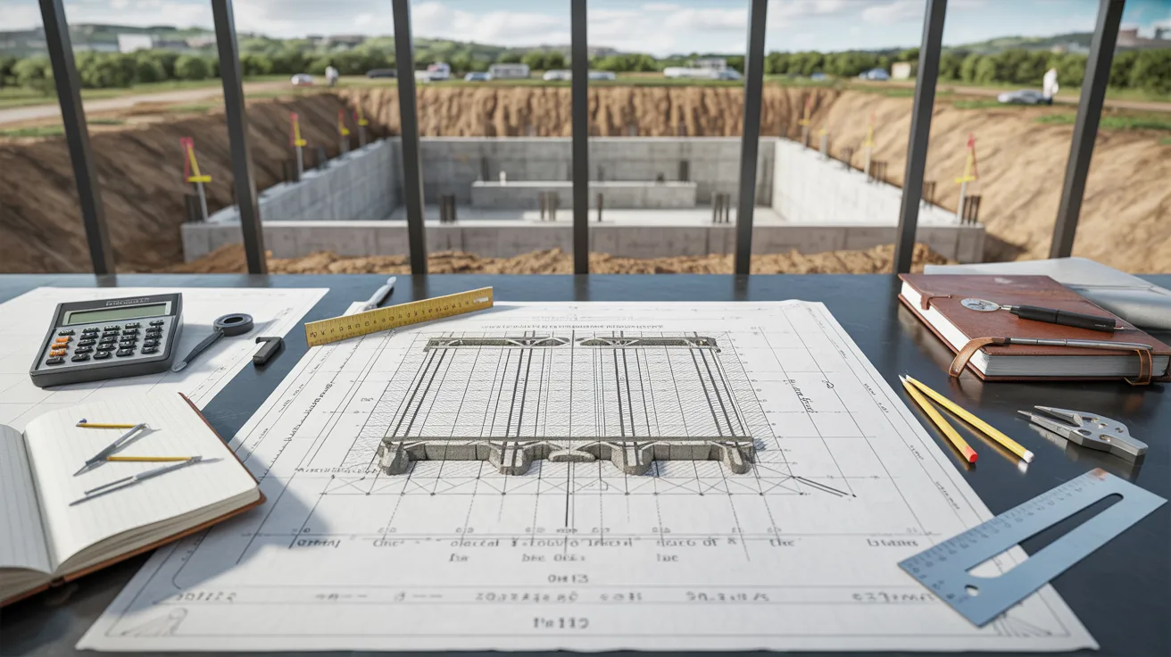
Step-by-Step Retaining Wall Footing Design Process
Work through these six steps in order to move from raw site data to a fully checked and documented footing design.
Step 1: Determine Soil Properties
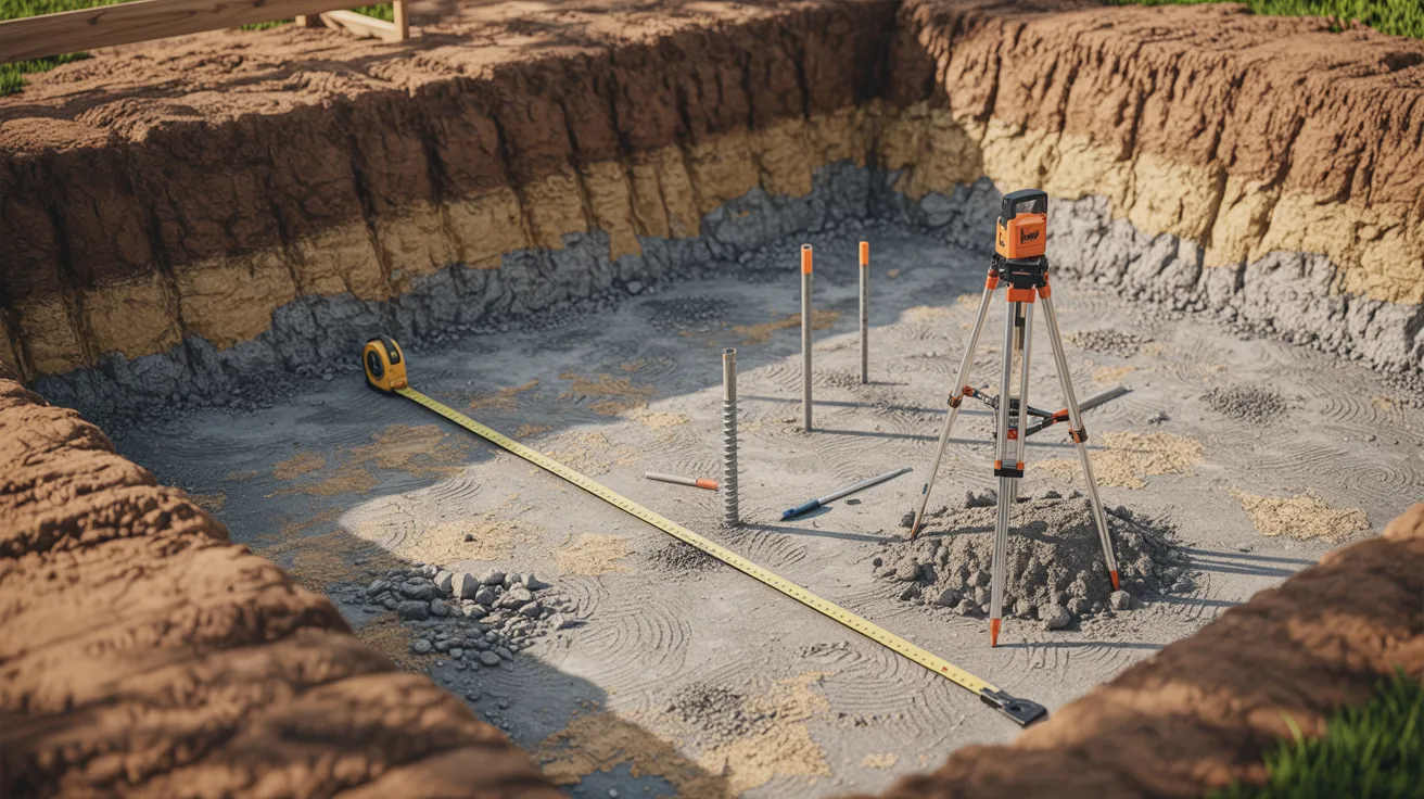
Start by collecting soil data from a geotechnical report or site investigation.
You need the unit weight of the retained soil, the internal friction angle, and the allowable bearing capacity at the footing depth.
These values feed directly into your lateral pressure and bearing calculations.
Using assumed or guessed values at this stage will throw off every number that follows. Accurate soil data is the starting point of a reliable design.
Step 2: Assign Preliminary Footing Dimensions
Use the ACI design ratios to set your first set of dimensions. Calculate the base width, toe length, heel length, and footing thickness based on total wall height.
Write these numbers down clearly before moving forward. You will likely adjust them after the stability checks, but having a defined starting point keeps the process organized.
Do not try to optimize here. The goal is to get reasonable numbers on paper so the calculations can begin.
Step 3: Calculate Loads and Moments
List every force acting on the footing: lateral earth pressure, surcharge loads, wall self-weight, soil weight on the heel, and hydrostatic pressure if drainage is limited.
Calculate the moment that each force creates about the toe of the footing. Separate the overturning moments from the resisting moments.
These values will feed directly into the stability checks in the next step. Be precise with your numbers. Small errors here can lead to a design that fails where it should have held.
Step 4: Perform Stability Checks (Overturning, Sliding, Bearing)
Divide the total resisting moment by the total overturning moment to get the overturning factor. Divide the total horizontal resisting force by the total driving force to get the sliding factor.
Calculate the resultant bearing pressure under the footing and compare it to the allowable soil bearing capacity. All three factors must meet their minimum values.
If any check fails, go back to Step 2, adjust the dimensions, and recalculate before moving forward.
Step 5: Design Reinforcement and Footing Sections
Once the geometry is confirmed, calculate the bending moments and shear forces in the stem, toe, and heel. Use ACI 318 strength design to find the required steel area in each section.
Select bar sizes and spacing that meet both strength requirements and minimum reinforcement ratios. Check that all bars have enough development length to be properly anchored.
Review the shear capacity of the footing to confirm that the thickness is sufficient without needing stirrups or additional ties.
Design Codes and References
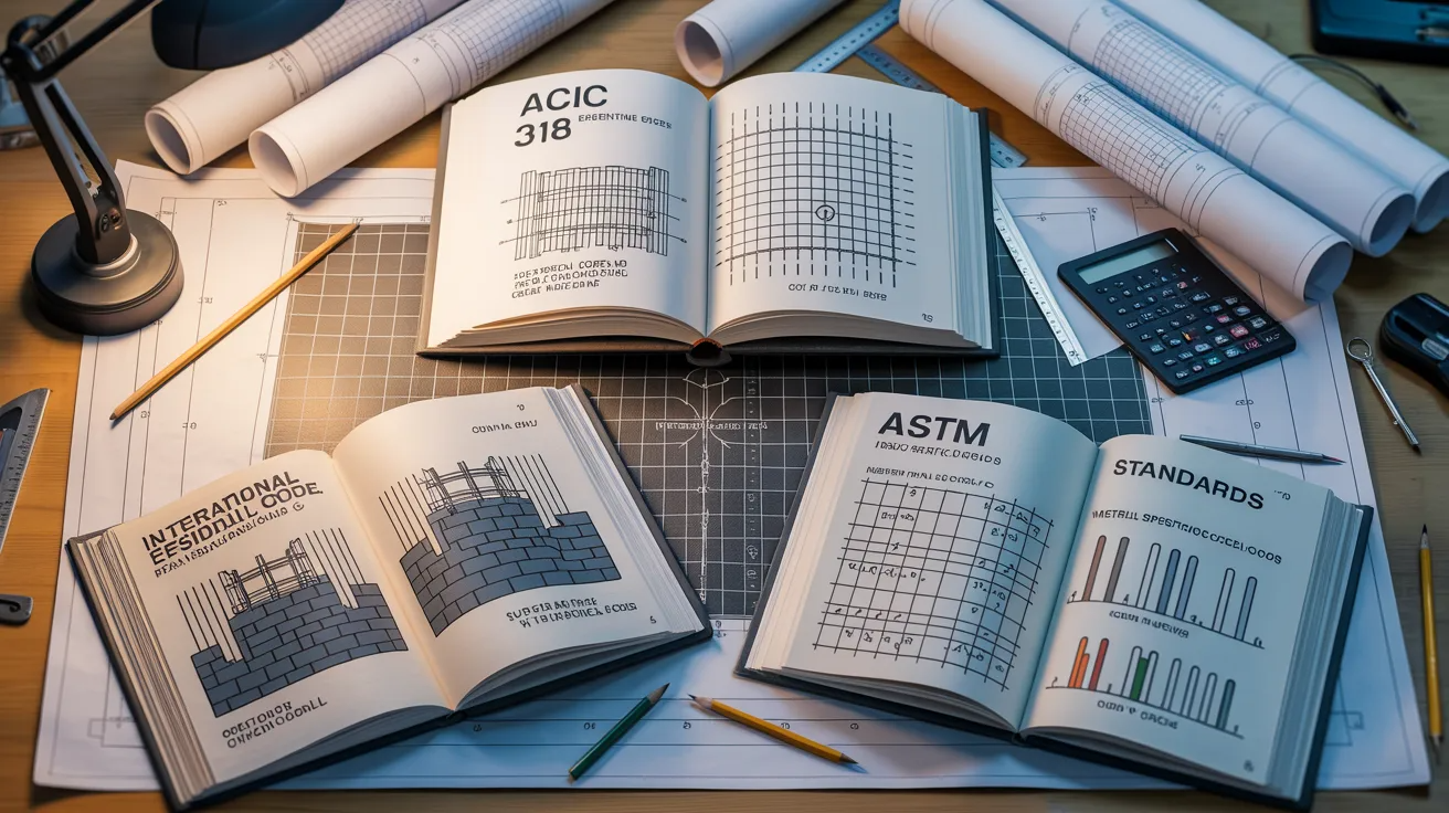
Three key documents guide retaining wall footing design in the United States.
The American Concrete Institute publishes ACI 318, which covers structural design of concrete elements including footings, stems, and reinforcement requirements.
It is the primary reference for sizing steel and checking strength in all cast-in-place concrete work.
The International Residential Code sets minimum requirements for residential retaining walls, including drainage and wall height limits.
ASTM International provides material standards for concrete, rebar, and aggregates used in construction.
I always cross-reference all three on any concrete wall project to make sure nothing important is missed and the design holds up under review.
Conclusion
Retaining wall footing design does not have to feel overwhelming. I broke it down step by step here so you can follow the same process I use.
Start with your soil data, set your dimensions, run the stability checks, and finalize your reinforcement.
The process is repeatable once you understand it.
Did this guide help you? Drop a comment below, share it with your team, or bookmark it for your next project. You got this.
Frequently Asked Questions
How deep should a retaining wall footing be?
Place it below the frost line, at least 12 inches thick.
What is the minimum base width for a retaining wall footing?
ACI recommends 0.4 to 0.7 times the total wall height.
Do I need a shear key under the footing?
Yes, when the sliding factor of safety drops below 1.5.
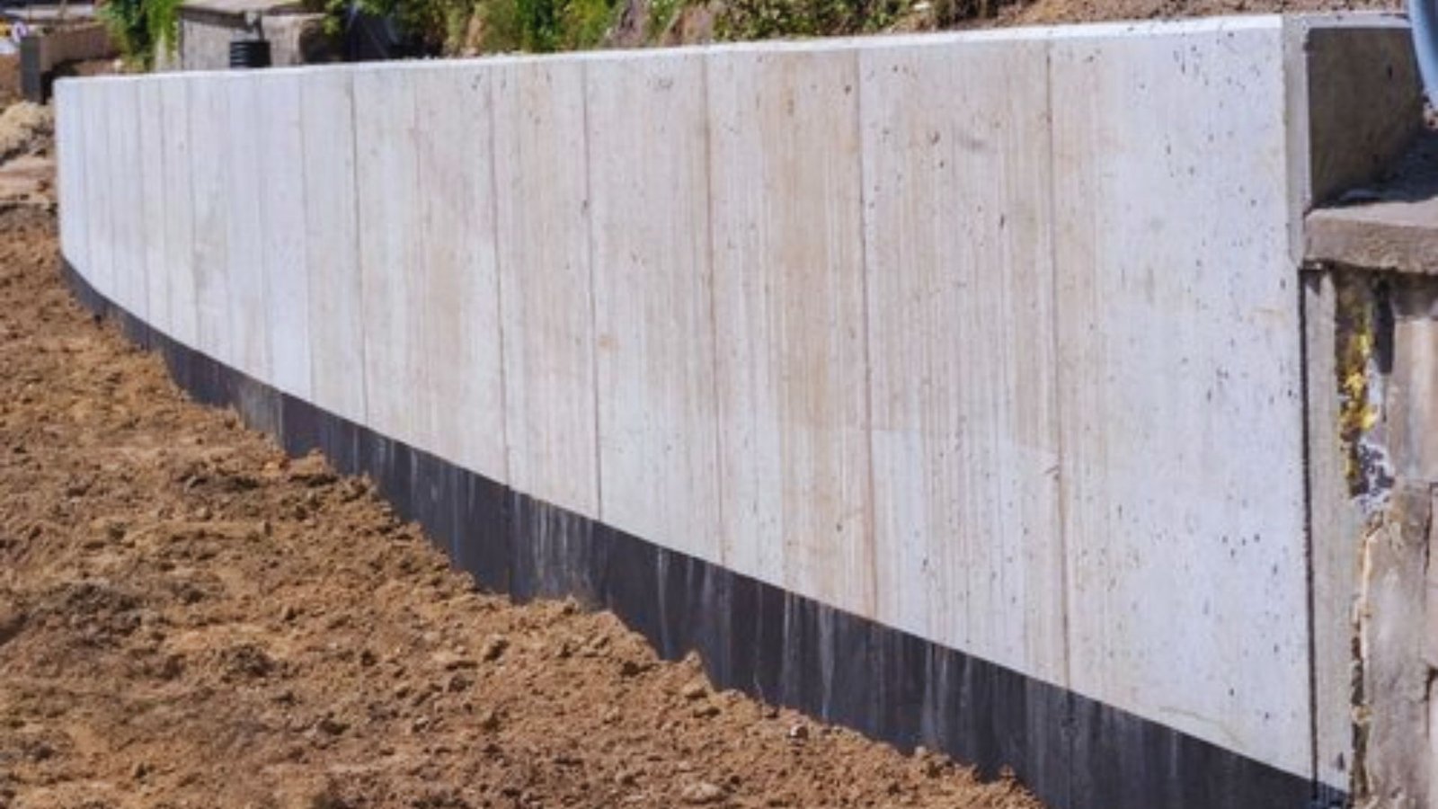
How does poor drainage affect footing design?
It increases hydrostatic pressure, which adds to the lateral load on the footing.
Can I design a retaining wall footing without a geotechnical report?
No, soil data controls every load and stability calculation in the design.